Fabrication 2 - Kanchanjunga Apartments - Sectional Model at 1:50

 Kanchanjunga Apartments were Charles Correas epitome of climate responsive architecture. As seen in the diagram alongside, the units were designed with varying opening sizes and varying slab cear heights. These helped wind move through the apartments, helping keep it cool throughout the year, in Mumbais temperate climate. Plywood was used comprehensively in this model, so that the final product is precise which accurately represent the geometry of the component chosen.
The photograph of the model above represents the section sketched by the master himself. It is interesting to note that inspite of the varying single and double heights, the upper slab profile is identical to the lower slab profile, which shows the possible repitition of the units above each other and also speaks about them interlocking togeter.

The most challenging part of this assignment would be the coordinatino of the box/finger joint. It is the feature around which the modelling process has revolved largely. When using this form of joinery and plywood, due to their rigidity of form one can either get the component a 100% right, or 100% wrong, there is no middle ground or room for error. A few samples of the joints and openings have been shown below.


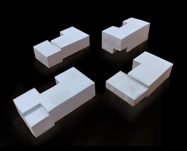
Isometric views of the model.


The side facades also help us understnad the ratio of openings to one another. There are some double height openings on the far ends and other mostly single height window openings on each floor, the smallest openings are the ventilation window for the toilets. These facades have been shown below.


As an experiment, addition of lights to the model was looked at because the inner spaces were dark and not visible easily, unless on close inspection. Trying some soldering with aqua 3mm LED 4000mcd clear, kynar wire black and red silver plated 0.254 mm dia, 2k Ohm 0.5 watt metal film resistor, it was possible to make a loop. As the 9v battery would supply excessive energy to the 3mm LED light, it was necessary to also use a resistor on the positive side so that the excessive current flow is stopped. The loop connected the positive side of the battery-resistor-led-negative end of the 9v alkaline battery. Upon successful soldiering of these joints and we were able to use the light and it could be placed anywhere in the darker spaces within the model. For future additions, many LEDs could be connected in a loop to the previous one, and the loop could span from window to window and also all the rear darker spaces in the model. This connection needs to be made and established complete with the soldering and fixing of the lights in place before the final model is closed. The battery should be allowed to be put in last/removed/changed.
The image below shows the placement of the light in few of the darker rooms and the effects it has on the model and the spaces surrounding it.


The humans that were 3D printed for the use in this model, so that it gives a good human scale understanding to the user.
Comments
Post a Comment